
Wholesale & Quote
Orders & Worldwide
Orders & Worldwide
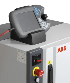
Does this look familiar? Even with careful use, accidental drops, excessive pressure, or impacts can damage the keypad membrane, connectors, lock mechanism, or emergency stop button, leaving your teach pendant in a "battle-worn" state. Many users continue using it until it completely fails.


Other frequent faults include:
Black screen/unresponsive operation
Flickering, cracked, or blank display
Freezing at startup, frequent E-stop alarms, lock head errors
Damaged keypad chips, motherboard failures, or constant yellow indicator lights

JZRCR-NPP01-1 (NX100)
JZRCR-YPP01-1 (DX100)
JZRCR-YPP21-1 (DX200)
JZRCR-APP01-1 (YRC1000)
JZNC-XPP02B (XRC)
When a teach pendant malfunctions or reaches its lifespan, repair or replacement is necessary. Below is a detailed disassembly and replacement procedure.

WARNING:
Perform disassembly/replacement only under professional guidance.
Non-technical personnel should contact certified technicians or the manufacturer to avoid secondary damage.
Unscrew the rear cover screws.
Carefully open the cover (note internal cables to avoid damage).
Photograph the internal structure and cable layout for reference.
Disconnect the enable button cable.
Remove the enable button assembly.
Lift the rubber sleeve upward to extract it.
Press the white button on the lower right.
Rotate counterclockwise until the label faces upward, then remove.
Unscrew the black nuts and washers.
Label components to avoid misplacement.

Remove the black nuts and washers.

Detach the mode switch board.
Unscrew the 4 mainboard screws.
Disconnect all ribbon cables (marked with ○).
Unscrew the 4 LCD mounting screws.
Extract the touchscreen-LCD assembly.
Remove the foam frame.
Remove all screws and disconnect cables.
Peel off the damaged keypad membrane.
Press out all small buttons from the keypad.
Unscrew the large nut on the cable connector.
Remove internal screws to fully extract the cable.

Follow the reverse order of disassembly, paying attention to:
Ensure proper alignment of ribbon cables.
Align the lock head with the manual position using a key.
Reinstall washers and nuts.
Verify all switch positions with the key.
Reattach black nuts and washers in sequence.
Release the E-stop button.
Align the label upward and rotate clockwise to install.
Reinstall buttons into the new housing.
Apply a new keypad membrane.
Mount the touchscreen assembly.
Reinstall the foam frame.
Secure the touchscreen-LCD assembly.
Reconnect all ribbon cables to the mainboard.

Install a new rubber sleeve.
Reconnect the enable button cable.
Reattach the rear housing and carrying strap.
Perform a full test to confirm all functions (buttons, screen, E-stop, etc.).
Common Replacement Parts
We supply:
New housings
Lock heads
Touch panels
Keypad membranes
Carrying straps
Enable button sleeves
Emergency stop buttons
Start/Hold buttons

0 de 3 itens selecionados
Selecione o primeiro item para comparar
Selecione o segundo item para comparar
Selecione o terceiro item para comparar
Deixe um comentário