I. Introduction
1. What is ROBOGUIDE?
ROBOGUIDE is a simulation software for developing Nachi robots. It supports offline programming and simulation functions, allowing users to design and debug robot tasks and programs in a virtual environment, thereby improving work efficiency and significantly reducing on-site debugging time and related functional costs. The features of ROBOGUIDE include analyzing the user interface and rich functions such as collision detection, load calculation, and cycle time evaluation, enabling engineers to complete program design without touching the actual robot. Additionally, ROBOGUIDE can export simulation animation videos and add custom logos to the video interface, making it convenient for users to view the simulation operation of the robot workstation or production line. In summary, ROBOGUIDE is a powerful and easy-to-use robot simulation software, widely evaluated in the field of robot programming and simulation.
2. How to connect a FANUC teach pendant to ROBOGUIDE?
This might be an exciting "Wow!!" moment. A long time ago, I saw someone on a forum who had connected an actual teach pendant to RG, but when I asked the person who posted it, they needed to purchase a cable made by FANUC. However, FANUC China did not sell this cable, so I stopped researching it. But now, you can make such a cable at a low cost.

This tutorial uses an RJ-45 100MB Ethernet cable. Please ensure that the teach pendant is of the following specifications (V8 and above systems):
A05B-2518-C307#Exxx
A05B-2518-C200#Jxxx
A05B-2518-C304#Jxxx
A05B-2256-C100#Exx
A05B-2256-C101#Jxx
A05B-2255-C102#Exx
A05B-2255-C200#Exx
For teach pendants of controllers 30iA and earlier, an RS-232 full-duplex mode is required for connection. This article will not support earlier versions of the teach pendant.
The pin definition of the 30iB series controller teach pendant cable and the connection to the crystal head are shown in the figure below. Power supply uses a DC24V power supply with overcurrent and overvoltage protection functions, and the output power is around 15W-30W to power the teach pendant. After correctly connecting according to the connection diagram, plug the crystal head into the computer's network port. If there is no network port, you can use an expansion dock or Ethernet to USB.

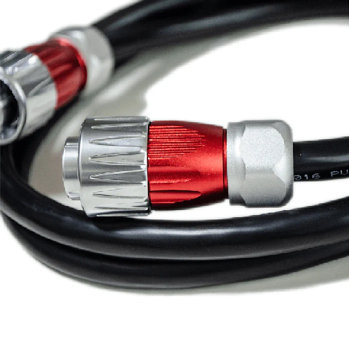
Appearance of the teach pendant cable:

II. Connection Steps
1.Hardware Connection:
1. Connect the cable to the iPendant.
2. Connect the Ethernet connector side of the cable to the network hub connected to the PC or directly to the PC.
3. Connect the DC24V power supply to the power input terminal of the cable.
2.ROBOGUIDE Settings
In the opened work cell, select Tools - Options
In the teach interface, check the box for using the actual iPendant and slide the virtual robot time to the far left at 100, then click Apply. Turn on the teach pendant, set the system variable $VIRTUALTIME to 6, and after setting, reopen this work cell.
At this time, hold down the SHIFT, i, POSN buttons on the teach pendant and turn on the 24V power. The teach pendant will enter the boot interface. (For 30iA teach pendants, hold down POSN, F3, enter 2, PREV, and press F5)
 When the following interface appears, use the teach pendant cursor buttons to select RoboGuideMode and press the ENTER button.
 At this point, you will enter the ROBOGUIDE connection wizard interface:
 Select the second item and choose the method of specifying the iP address as using a static iP, and configure iPV4. This must be consistent with the local iPV4 subnet. This is basically the same as the configuration of iP in the FANUC 30iA 2DiRVision Vision - Connection article, only the interface is different.
 Select the connected Ethernet adapter and manually assign the computer's iPV4 address.
After configuring both the computer side and the teach pendant side, click Next on the teach pendant interface, and the following interface will appear.
 Select the connected robot and click Next. At this point, the teach pendant will enter the system.


Laisser un commentaire