
Wholesale & Quote
Orders & Worldwide
Orders & Worldwide

In the realm of modern industrial automation, the robotic control system is pivotal for achieving precise and efficient production. The control cabinet, as the core of the robotic control system, plays an essential role.
The control system typically consists of a control cabinet, the robot's mechanical structure, and connecting cables. The control cabinet acts as the brain of the entire system, responsible for issuing commands and processing data, while the robot's mechanical structure is the physical part that executes these commands. The connecting cables link the control cabinet with the robot's mechanical structure, ensuring the transmission of information and energy.

Industrial robots are composed of multiple joints and corresponding servo motors, with each joint accounting for one degree of freedom of the robot, enabling it to perform a variety of complex movements flexibly.
Each joint of the robot is controlled by a corresponding servo motor. These motors receive instructions from the control cabinet and precisely drive the mechanical arm to execute corresponding movements. Through programming, robots can perform tasks that are highly repetitive and require high precision, such as welding, assembly, handling, and more.
As technology advances, future robots will become more intelligent, capable of autonomous learning and adapting to more complex work environments. The continuous progress in robotics technology will undoubtedly bring more possibilities and innovations to industrial manufacturing.
The base serves as the foundation of the robot, supporting the entire weight of the robot and ensuring that the robot does not shift or tip during movement. A sturdy base can reduce vibrations caused by high-speed movements or load-bearing, thereby improving operational accuracy. The design of the base must consider the safety of robot operations to prevent tipping or injury due to accidental collisions or operational errors.
Grounding Terminal: The base is equipped with a grounding terminal to ensure the electrical safety of the robot system. Through the grounding terminal, the electrical part of the robot can be connected to the ground to prevent electrical faults and leakage.

The control cabinet typically contains controllers, power modules, input/output interfaces, and safety systems, connected to the robot's body through power cables, signal cables, and grounding wires. The entire control process is as follows: engineers write motion commands for the robot using programming languages or graphical interfaces. After receiving the program, the control cabinet converts it into specific control signals. The signal cables transmit the control signals to the robot's mechanical structure, driving motors and other actuators. The robot's motion status is fed back to the control cabinet through sensors, and the controller adjusts the commands based on the feedback to ensure precise control.

The control cabinet achieves precise control of industrial robots through sophisticated electronic and software systems. It not only improves production efficiency but also ensures the safety and reliability of operations. With the continuous advancement of technology, future control systems will become more intelligent, capable of performing more complex tasks and achieving higher levels of automation.
The internal structure of the R-30iB A and B cabinets demonstrates the complexity and versatility of industrial robot control cabinets. These components work together to ensure stable operation, precise control, and electrical safety of the robot system. As technology evolves, the design of control cabinets is also continuously optimized to meet higher performance requirements and a wider range of application scenarios.

The external structure of the control cabinet, especially the components on the back, plays a crucial role in the stable operation, heat dissipation efficiency, and electrical safety of the entire robot system. The rear fan unit helps with cooling the control cabinet, the regeneration resistor protects the system from regenerated energy, and the transformer ensures the stability and safety of the power supply system. The meticulous design and layout of these components enable the control cabinet to operate reliably in various industrial environments.
Symptoms:
Potential Causes:
Symptoms:
Potential Causes:
Symptoms:
Potential Causes:
Symptoms:
Potential Causes:
When the robot in normal use reaches an operating time of 10,000 hours or has been in use for 3 years, it is necessary to replace the internal lubricating oil of the main reducer. Depending on the actual operating environment of the FANUC robot, the maintenance interval may be appropriately shortened.
Lubricating oil should be added to both sides of the SHAFT of the robot's main balance cylinder once every six months.
The robot's main battery (recommended by FANUC) needs to be replaced once a year.
The motherboard battery inside the control cabinet should be replaced once every 2 or 3 years.
Tool List: Hex key set, oil gun HG-70, manual oil gun (for balance cylinder), appropriate amount of rags, appropriate amount of trash bags.
Safety Supplies List: Safety helmet, safety padlock, gloves, safety shoes, reflective vest, safety rope (for climbing).
Conduct an MC backup and an IMG backup for the robot.
Switch the robot to manual mode.
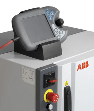
Set the key switch on the control cabinet to T1/T2, ensure the teach pendant's ON/OFF switch is in the ON position, and press the emergency stop button.
Note: Do not turn off the robot's power when replacing the battery.
Adjust the robot to a refueling posture: Slowly move each axis individually to the specified posture (the required position for each axis).
Open the oil outlets of each axis (unscrew the outlet screws with a hex key).
Note: The oil outlet for the J6 axis needs to be opened after the J5 axis has been oiled and the oil outlet is closed.
Use a manual oil gun to add oil to the oil inlets of each axis (or a pneumatic gun with pressure controlled around 0.15MPa can be used).
Add oil to the left and right SHAFT of the balance cylinder.
Manually move each axis for 10-20 minutes. After releasing the internal pressure of the reducer, screw back the outlet screws.
Open the battery cover and replace the main battery.
Note: Pay attention to the positive and negative installation direction of the battery. Do not turn off the robot's power when replacing the battery.
Replace the control cabinet battery.
Note: Do not turn off the robot's power when replacing the battery.
Clean up the tools and trash at the site, then clear the external emergency stop alarm, and the robot resumes production.

0 von 3 Elementen ausgewählt
Wählen Sie das erste zu vergleichende Element aus
Wählen Sie das zweite zu vergleichende Element aus
Wählen Sie das dritte Element zum Vergleichen aus
Einen Kommentar hinterlassen