
Wholesale & Quote
Orders & Worldwide
Orders & Worldwide

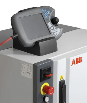
The IRC5 compact control cabinet highly condenses the functions of the IRC5, such as excellent motion control capabilities and highly flexible RAPID language. Crucially, it saves more space than ordinary control cabinets.
The IRC5 compact control cabinet uses advanced dynamic simulation to achieve accurate and efficient control and predictable optimization performance, achieving "what you program is what you get" without the need for programmer debugging. It is widely used in automated production lines, digital workshops, and other fields.
Model: IRC5 M2004 Compact Control Cabinet
Fault Phenomenon: The system does not boot up, and the main unit alarms for low CMOS battery voltage.
Detection Results: The main board is damaged, and the host communication is faulty.

Ensure the system's main power supply is on and within the specified limits.
Ensure the main transformer in the drive module is correctly connected to the existing power supply voltage.
Ensure the main switch is turned on.
Ensure the power supply to the control module and the drive module does not exceed the specified limits.
Ensure the main power supply is working normally and the voltage meets the controller's requirements.
Ensure the main transformer is correctly connected to the power supply voltage.
Make sure the main fuse in the drive module is not blown.
If the control module is working normally and the main switch of the drive module is turned on, but the drive module still cannot start, ensure all connections between the drive module and the control module are correct.
Check if the program contains logical instructions, as such programs can cause execution loops when conditions are not met.
Ensure the I/O update interval value for each I/O board is not too low.
Check for a large number of cross-connections or I/O communications between the PLC and the robot system.
Try to edit the PLC program with event-driven instructions instead of using loop instructions.
Ensure the main switch is turned on.
Ensure the system is powered.
Check the main transformer connection.
Ensure the contactor is open-circuited and closes when executing instructions.
Disconnect the connector from the power supply of the drive module and measure the incoming voltage.
If the power input voltage is correct but the LEDs still do not work, replace the drive module power supply.
Ensure the circuit breaker in the Control Module has not tripped.
Ensure the ground fault protection has not tripped.
Ensure the power supply of the robot system meets the specification requirements.
Ensure the transformer supplying power to the socket is correctly connected, i.e., the input and output voltages meet the specification requirements.

Ensure the robot tool and work object are correctly defined.
Check the position of the rotary encoder.
If necessary, recalibrate the robot axis.
Locate the faulty bearings by tracing the noise.
Locate the faulty motors by tracing the noise. Analyze the robot TCP path to determine which axis and motor may be faulty.
Check if the parallel bars are correctly aligned.
Ensure the correct type of robot is connected according to the specifications in the configuration file.
Ensure the robot brake can operate correctly.
The article and images are from the internet and are copyrighted by the original authors.


0 of 3 items selected
Leave a comment on this topi