Ⅰ. KUKA Robot System Components
1. Introduction to KUKA Robots
KUKA robots have earned a reputation for their exceptional precision and adaptability in industrial automation. These cutting-edge devices are capable of executing a multitude of tasks, ranging from welding and assembly to material handling and precision machining. The essence of a KUKA robot lies in its advanced system architecture that harmonizes hardware and software components to achieve superior performance and dependability.
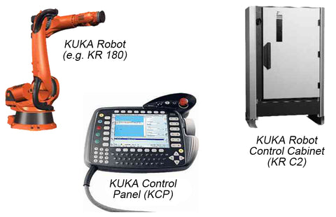
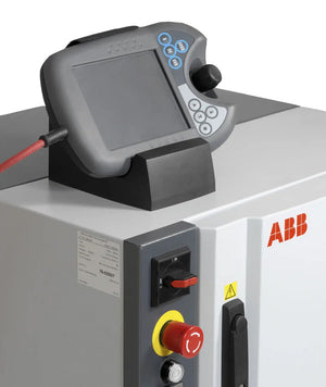
2. KUKA Control Panel (KCP)
The KUKA Control Panel (KCP) acts as the central hub for KUKA robots, offering operators a user-friendly platform to oversee and direct robotic functions. The KCP is crafted with a focus on ergonomic design, ensuring that it is both comfortable and efficient for use.
This panel boasts a high-definition touch-screen display that facilitates effortless navigation through the robot's operational system. It provides a crisp visualization of the robot's movements and status, allowing for real-time monitoring and operational adjustments. The KCP also incorporates advanced programming capabilities, enabling users to devise intricate robotic sequences with exactitude.
3. KUKA Robot Control Cabinet (KR C2)
The KUKA Robot Control Cabinet (KR C2) is the pivotal component of the KUKA robotic system, containing the central processing unit and power supply that propel the robot's functions.
The KR C2 is compact yet potent, featuring sophisticated processors capable of managing the intricate computations necessary for accurate robotic control. It includes a robust power supply unit that ensures stable energy delivery to the robot, even under variable conditions.
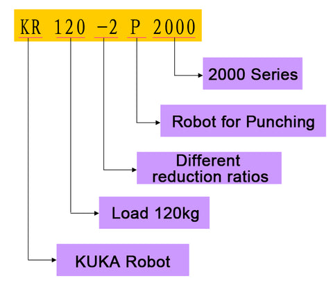
Ⅱ. KUKA Robot Models
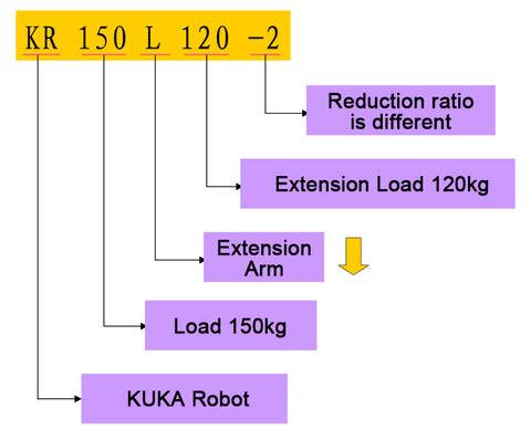
Explanation
1. KRXXX is standard, but the L120-2 at the back is not. For example, the robot model of 34 lines is KR120-2P2000.
2. The load refers to the TCP point capacity, 150kg refers to the 6-axis center point capacity; and 120kg is to increase the extension arm according to the new TCP point capacity (torque increase).
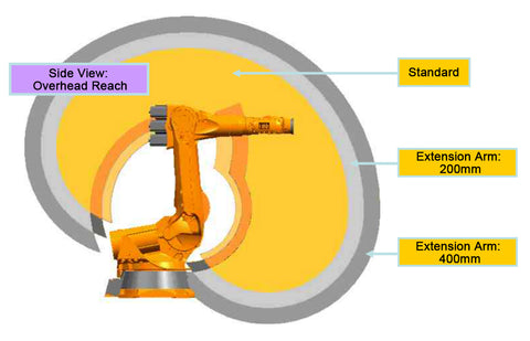
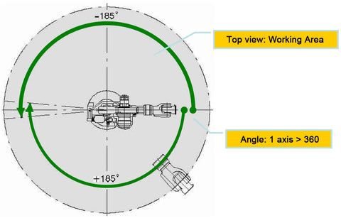
Ⅲ. Working area of KUKA Robot
Side View:
Top View:
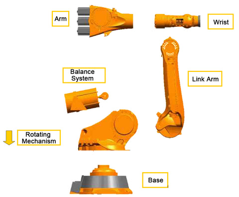
Ⅳ. KUKA Robot Structure
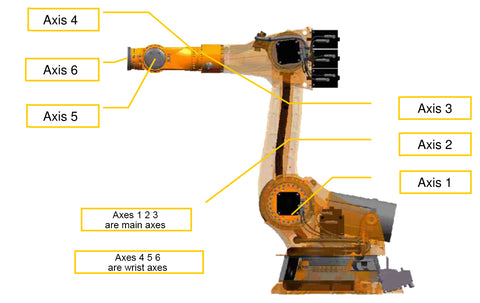
Axes1 2 3 are main axes, Axes4 5 6 are wrist axes
The article and images are from the internet and are copyrighted by the original authors.


Leave a comment on this topi